
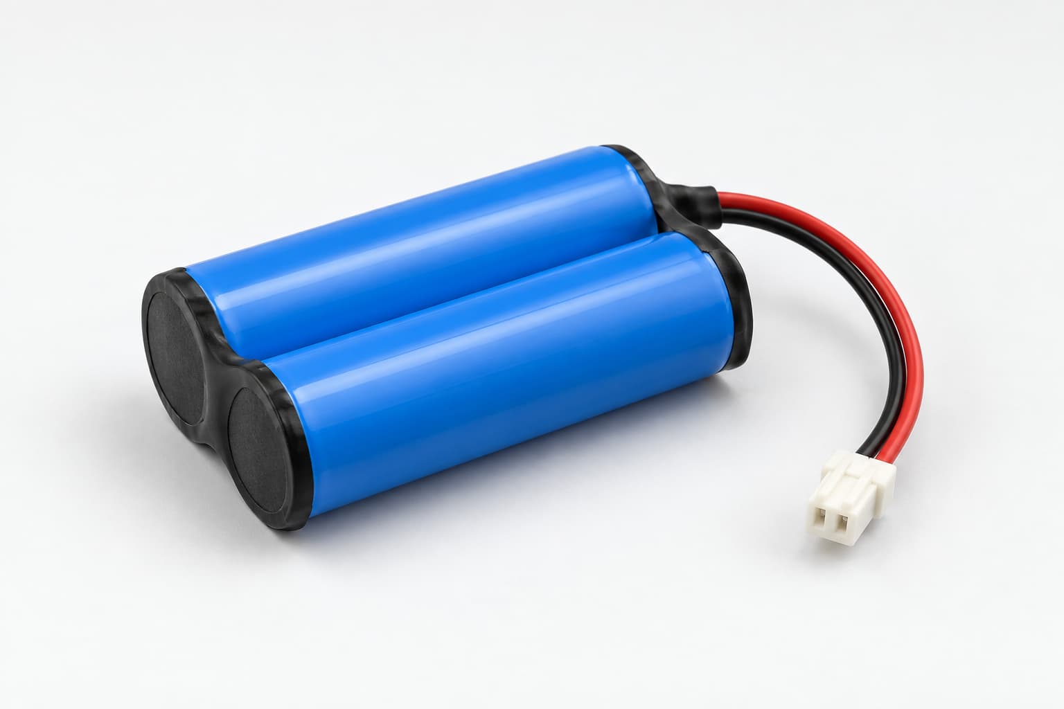
An effective 18650 battery pack design for OEM devices starts with measured product requirements, not a preferred cell or capacity label. The pack must support the device voltage, peak load, runtime, charging method, available space, operating temperature, and target market. It must also remain reproducible when the project moves from prototypes to regular production.
Define the OEM 18650 Battery Pack Requirements
Measure sleep current, typical current, maximum continuous current, peak current, and peak duration in the real device. Motors, pumps, wireless transmitters, heaters, and displays may create short peaks that average-current readings miss. Record the lowest device-input voltage that still allows stable operation.
Define runtime with a repeatable duty cycle. State the firmware version, device mode, temperature, initial state of charge, and discharge endpoint. A target such as ten hours is incomplete unless you also define the operating pattern.
- Nominal and maximum pack voltage
- Continuous and peak-current demand
- Required runtime and test cycle
- Maximum finished-pack dimensions
- Charging input and target charge time
- Connector, pinout, polarity, and wire length
- Operating and storage temperatures
- Expected volume and target markets
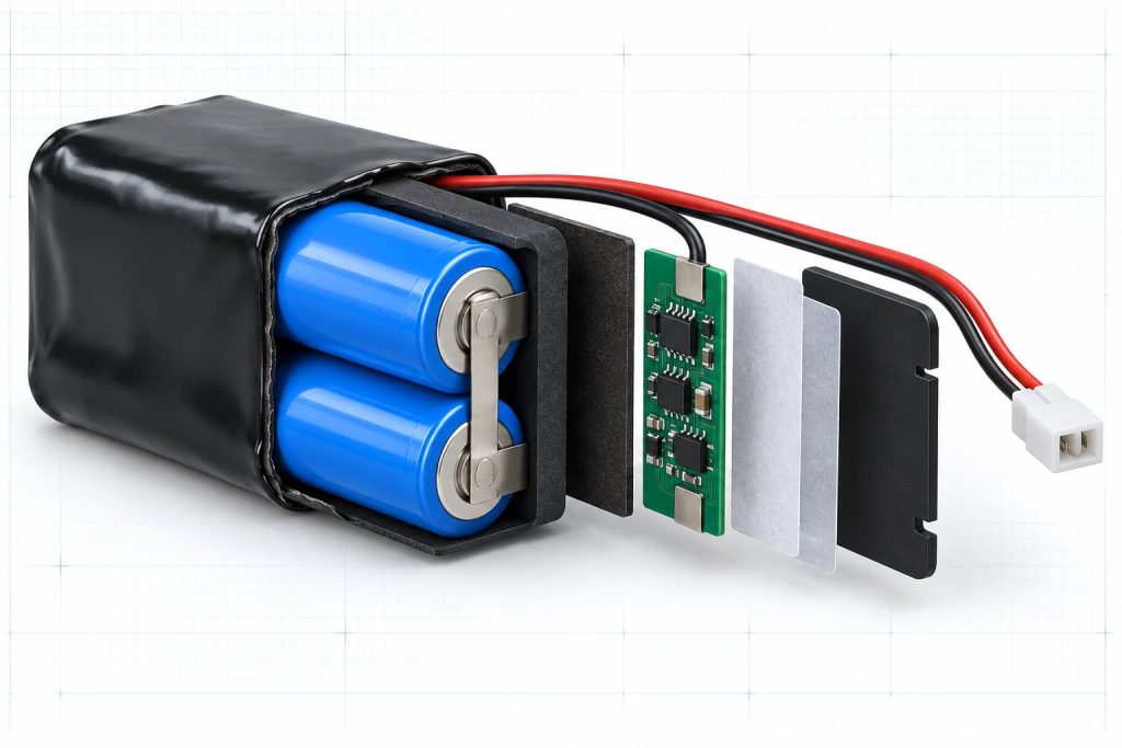
Select the 18650 Cell and Pack Configuration
The series count sets pack voltage, while the parallel count affects capacity and current capability. Check the device across the complete battery voltage range. A pack that works when fully charged may reset near the discharge limit if cell resistance and current-path losses create excessive voltage drop.
Compare candidate cells using capacity, internal resistance, pulse performance, cycle life, temperature behavior, lot consistency, and long-term availability. Zenilove’s cylindrical battery range provides a starting point, but final selection should follow application testing.
Specify Protection Charging and Interfaces
Document overcharge, over-discharge, overcurrent, short-circuit, and temperature-protection settings. Include threshold tolerances, delay times, and recovery behavior. Protection set too close to normal startup demand may cause false shutdowns, while limits above the cell, wire, or connector capability may leave the system underprotected.
Confirm charger voltage, current, termination behavior, and operation while charging. Control the connector part number, pinout, polarity, wire gauge, and cable direction on the approved drawing.
The host device and battery pack should also have clearly assigned responsibilities. The pack may provide cell protection and temperature monitoring, while the device controls user warnings, charge commands, or low-battery shutdown. Documenting this boundary prevents both systems from assuming that the other will manage the same condition.
Control the Mechanical OEM Battery Specification
Define maximum finished dimensions, including cells, holders, protection board, insulation, labels, adhesive, wires, and connector. Review the installation path and the final cavity. The pack must be installable without pulling wires, stressing welds, or pressing against sharp enclosure features.
If the project needs a 5200mAh configuration, compare the proposed design with the 18650 5200mAh battery pack and confirm that its voltage, dimensions, current rating, and interface match the device.
Validate the 18650 Battery Pack in the Device
Build production-intent samples with the proposed cell, BMS, wiring, connector, insulation, and structure. Test capacity, peak-load voltage drop, protection response, charging, temperature, runtime, and low-state-of-charge operation in the finished device.
Assign an identification number to every sample and record the cell lot, drawing revision, protection-board revision, programmed parameters, connector, and build date. Match these records with the device hardware, firmware, enclosure, and charger used for testing. This traceability allows the team to identify which change caused an improvement or failure.
Start compliance planning before design freeze. The IEC 62133-2 standard describes safety requirements and tests for portable sealed secondary lithium cells and batteries. The applicable test plan still depends on the product and market.
Review Supply Continuity and Quality Controls
An OEM pack must remain available after the first approved sample. Ask how the supplier controls cell manufacturer, exact cell model, production lot, age, storage condition, and substitutions. Switching from one 18650 cell to another can change capacity, resistance, peak-current behavior, charging temperature, and cycle life even when the printed ratings look similar.
Define incoming inspection and end-of-line checks before volume production. Useful controls may include open-circuit voltage, internal resistance, pack voltage, polarity, insulation, protection response, connector fit, and a functional load test. Set acceptance limits and record results against the pack serial number or batch so you can trace field issues to controlled production data.
The purchase specification should also require advance notification for changes to the cell, BMS components, firmware, welding process, insulation materials, connector, cable, label, or manufacturing location. Test approved alternatives in the device before they enter regular production.
Freeze the 18650 Battery Pack Design for OEM Production
Approve the electrical specification, drawings, bill of materials, protection settings, test methods, sample IDs, and change-notification rules. Then use a pilot build to verify welding, insulation, programming, cable routing, labeling, traceability, and end-of-line testing.
A complete OEM specification gives engineering, purchasing, quality, and manufacturing the same measurable definition of the approved pack. Zenilove’s Custom Battery Pack process can support this work from cell selection through pilot production.
OEM 18650 Battery Pack Questions
Is Cell Capacity Enough to Select an 18650 Pack
No. Capacity affects runtime, but the pack must also match voltage, current, temperature, dimensions, charging, protection, connector, and service-life requirements. A high-capacity cell can still be unsuitable if it cannot support the device peak load or approved temperature range.
When Should the Specification Be Frozen
Freeze the specification after production-intent samples pass device-level electrical, thermal, mechanical, charging, and protection tests. The approved records should identify the exact cell, BMS, drawing, materials, connector, charger, firmware, and test limits used for acceptance.