
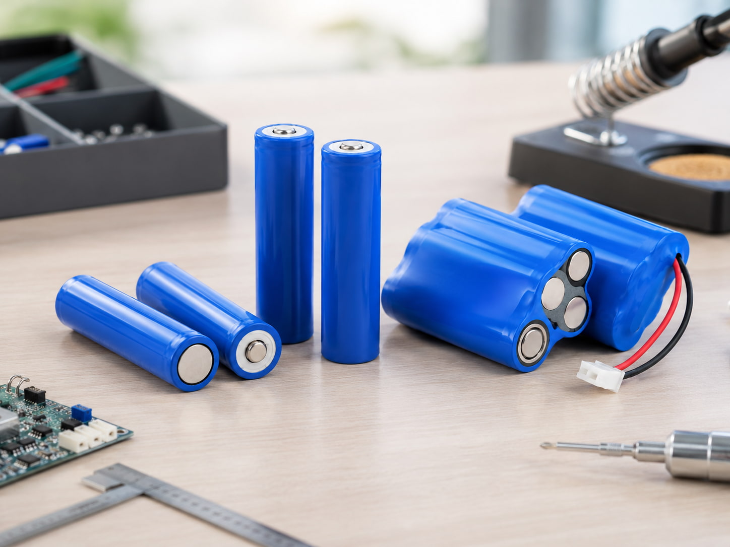
Choosing a 21700 battery pack for industrial equipment starts with the device, not the cell label. A suitable pack must deliver the required voltage and runtime, support peak current without excessive voltage drop, fit the available space, connect safely to the equipment, and remain reliable under the expected temperature, vibration, and charging conditions. Zenilove’s cylindrical battery solutions provide reference configurations for comparing cell formats, pack layouts, voltage platforms, and capacity options.
Match a 21700 Battery Pack for Industrial Equipment to the Electrical Load
Before selecting a pack, record the device’s operating voltage range, average current, peak current, peak duration, desired runtime, charging method, and low-voltage cutoff. These values form the battery specification. Specify a 21700 battery pack for industrial equipment based on measured device demand rather than an assumed current value.
Nominal voltage alone is not enough. A 3S lithium-ion pack made with 3.6V nominal cells is approximately 10.8V nominal, but it may reach 12.6V when fully charged. The equipment must tolerate the complete pack voltage range, not only the number printed on the label. Peak load matters as much as average load. Motors, pumps, radios, heaters, and actuators may draw short bursts several times higher than their normal operating current. The cells, BMS, wiring, and connector must all pass that current without nuisance shutdown, overheating, or unacceptable voltage sag.
Choose the Series and Parallel Configuration
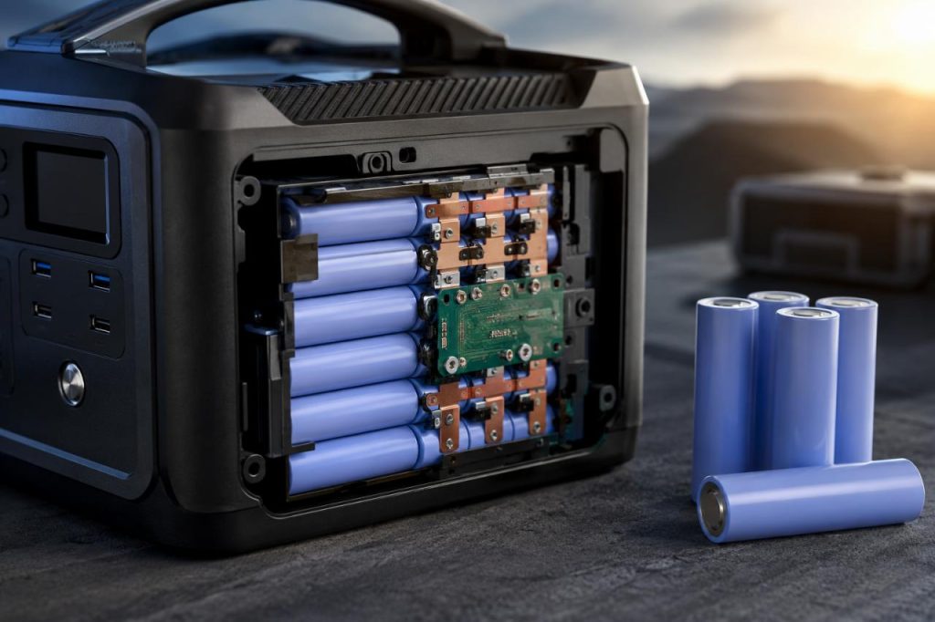
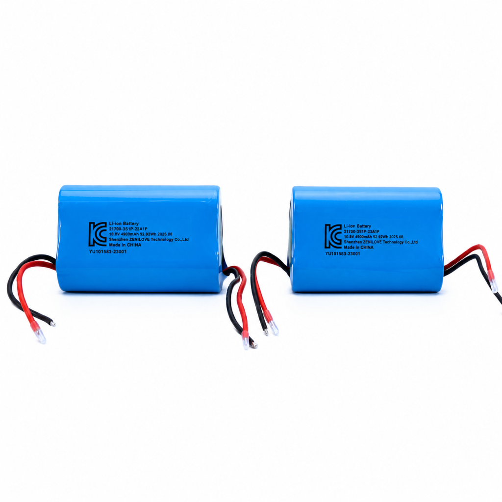
Cells connected in series increase pack voltage. Cells connected in parallel increase capacity and can share load current. For equipment designed around an approximately 10.8V nominal supply, common examples include 3S1P and 3S2P configurations. A 10.8V 3S1P 21700 battery pack contains three cells. If each cell is rated at 4900mAh, the pack remains approximately 4900mAh and stores about 52.92Wh at 10.8V nominal. A 10.8V 3S2P 21700 battery pack contains six cells. With the same cells, it provides approximately 9800mAh and 105.84Wh while maintaining the same nominal voltage. The larger configuration can offer longer runtime and lower current per cell, but it also requires more volume, adds weight, and usually takes longer to charge at the same charger current.
Estimate Runtime in Watt-Hours
Watt-hours provide a better comparison than amp-hours when evaluating devices or packs with different voltages. Calculate nominal energy as:
Energy (Wh) = nominal voltage (V) × capacity (Ah)
Then estimate ideal runtime by dividing pack energy by average device power. A 52.92Wh pack powering a 10W load has an ideal estimate of about 5.3 hours. Real runtime will be lower because of conversion losses, BMS cutoff, temperature, cell aging, and voltage drop under load.
Match the BMS to the Pack and Load
The battery management system must match the number of series groups and the cell chemistry. It should provide appropriate overcharge, over-discharge, overcurrent, and short-circuit protection. Temperature sensing may also be necessary, especially in enclosed products, high-current systems, or equipment used across a wide ambient range.
Check both continuous and peak discharge limits. A BMS advertised for a particular current may have conditions related to cooling, duration, or temperature. Its cutoff behavior must also work with the equipment’s startup surge. Protection limits should remain within the safe operating limits of the selected cells and conductors.
Verify Mechanical Fit and Pack Orientation
Industrial devices often impose stricter mechanical constraints than consumer products. Confirm available length, width, height, cable exit direction, connector clearance, mounting method, and service access. Leave room for insulation, cell holders, protection electronics, wires, strain relief, and manufacturing tolerances.
Select Wires and Connectors as Part of the Power Path
Select wire gauge based on continuous current, peak current, cable length, allowable voltage drop, temperature, insulation rating, and installation conditions. Short internal leads can still heat if they are undersized or poorly terminated. The connector must be rated for the actual current and number of mating cycles. It should also have suitable contact resistance, polarity control, locking behavior, environmental sealing, and compatibility with the assembly process.
Account for the Industrial Environment
Temperature affects available capacity, voltage sag, charge acceptance, and service life. Low temperatures can reduce usable energy, while high temperatures accelerate aging and may increase safety risk. Define storage, charging, and discharging temperature ranges separately.
Validate the 21700 Battery Pack for Industrial Equipment
Test a prototype pack with representative equipment, firmware, cables, and accessories. Measure startup current, steady-state current, connector temperature, voltage drop, runtime, charging behavior, and BMS cutoff behavior. Repeat important tests at relevant temperatures and at different states of charge. For safety requirements and test considerations, consult the applicable edition and scope of IEC 62133-2, together with any product-specific and transport requirements.
Practical Selection Checklist
- Confirm the full device voltage range and charger voltage.
- Measure average and peak current using the real duty cycle.
- Calculate required watt-hours with reserve margin.
- Select series and parallel configuration.
- Verify the current capability of the cell, BMS, wire, and connector.
- Check enclosure dimensions, cable routing, mounting, and service access.
- Define temperature, vibration, moisture, and compliance requirements.
- Validate prototypes in the actual equipment before production approval.
Frequently Asked Questions
Is a higher-capacity 21700 battery pack always better for industrial equipment?
No. Higher capacity can extend runtime, but it also increases size, weight, charging time, and cost. The best pack meets the duty cycle and reserve target, fits the equipment, and meets current and environmental requirements.
Can a 3S2P pack replace a 3S1P pack?
It may be electrically compatible because both can have the same nominal voltage, but the 3S2P pack is larger and heavier. You must still verify the charger, enclosure, mounting, BMS behavior, connector, and equipment cutoff.
What information should an OEM provide to a battery pack supplier?
Provide operating voltage, continuous and peak current, peak duration, runtime target, charging details, available space, connector requirements, cable length, environmental conditions, expected cycle life, compliance needs, and annual volume. Better input data leads to a safer and more accurate pack proposal. Always confirm final specifications against the target equipment and application conditions.