
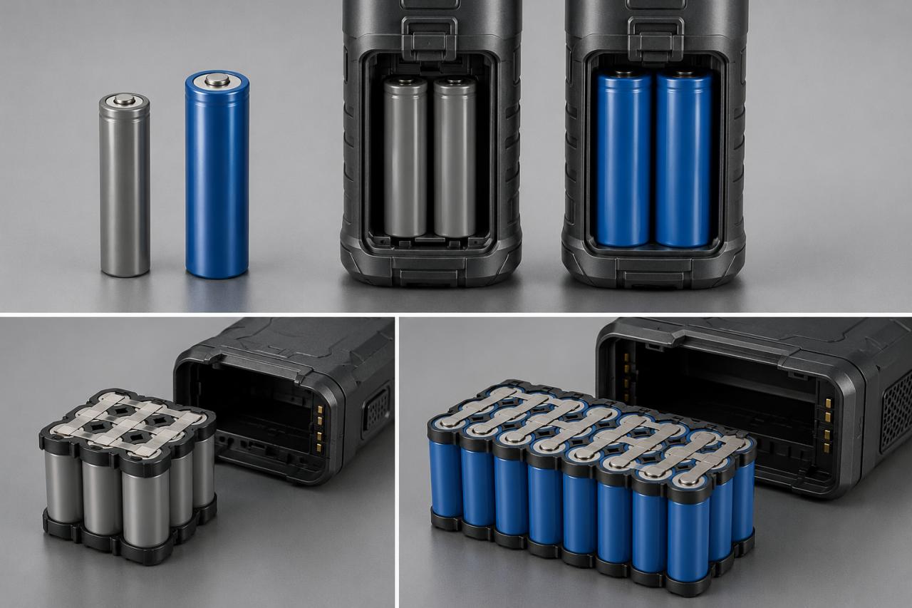
A custom cylindrical battery pack must match the device’s electrical requirements, available installation space, and connection method. Selecting a pack only by capacity can lead to incorrect voltage, limited output, installation problems, or connector mismatches. The selection should begin with four factors: voltage, capacity, size, and connector design. These requirements determine whether the pack should use an 18650 cylindrical battery, a larger 21700 cell, or multiple cells connected in series and parallel.
Terms such as cylindrical li ion battery, cylindrical lithium battery, cylindrical lithium ion battery, and cylinder batteries may appear in specifications. Regardless of the wording, the battery structure must follow the device requirements.
Custom Cylindrical Battery Pack Voltage Must Match the Device
Voltage determines how many cells need to be connected in series. A voltage that is too high may damage the device, while a voltage that is too low may prevent startup or cause unstable operation.
Compare Common Series Configurations
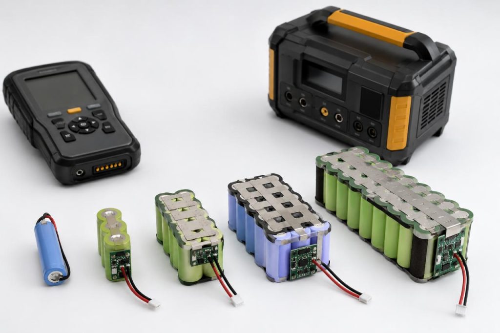
A typical cylindrical lithium ion battery has a nominal voltage of approximately 3.6V or 3.7V. Connecting cells in series increases the pack voltage.
| Configuration | Typical Nominal Voltage | Suitable Direction |
|---|---|---|
| 1S | 3.6V or 3.7V | Single-cell portable devices |
| 2S | 7.2V or 7.4V | Medium-voltage electronic equipment |
| 3S | 10.8V or 11.1V | Tools and industrial devices |
| 4S | 14.4V or 14.8V | Higher-voltage equipment |
Choose a 1S pack when the device is designed for a single lithium-ion cell. This configuration can support compact instruments, monitoring devices, and portable electronics. Choose a 2S pack only when the device input and charger support approximately 7.2V or 7.4V. A 3S configuration is more suitable for equipment designed around approximately 10.8V or 11.1V. Do not choose a higher-voltage pack simply because it stores more energy. Voltage must follow the device circuit first.
Check the Charger Before Selecting Voltage
The charger must match the series configuration. A charger designed for a 1S pack cannot safely charge a 3S pack.
Before selecting the voltage, confirm:
- Device operating voltage
- Acceptable input range
- Charger output voltage
- Charging method
- Low-voltage cutoff point
Choose the series configuration only after these values have been confirmed. This prevents the custom cylindrical battery pack from exceeding the device input range or using an incompatible charger.
Custom Cylindrical Battery Pack Capacity Should Follow Runtime
Capacity affects how long the device can operate between charges. However, mAh values should only be compared directly when the packs have the same nominal voltage.
Compare Common Capacity Options
| Battery Configuration | Nominal Voltage | Capacity | Suitable Direction |
|---|---|---|---|
| 18650 single cell | 3.6V | 2600mAh | Compact devices with moderate runtime |
| 18650 single cell | 3.6V | 3500mAh | Longer runtime in a similar format |
| 21700 single cell | 3.6V | 4900mAh | Higher capacity per cell |
| 18650 1S2P pack | 3.6V | 5200mAh | Longer runtime at single-cell voltage |
| 18650 1S3P pack | 3.6V | 7800mAh | Extended operating time |
| 18650 1S4P pack | 3.7V | 10400mAh | High-capacity devices with more space |
Choose a 2600mAh 18650 cylindrical battery when the device is compact and only needs moderate runtime.
Choose a 3500mAh 18650 cell when more runtime is required, but the housing must retain a similar cell format.
A 4900mAh 21700 cell is more suitable when the device can accept a larger diameter and length. It provides more capacity per cell and may reduce the number of parallel cells required.
Use Parallel Cells to Increase Capacity
Connecting cells in parallel increases capacity without raising nominal voltage. A 1S2P pack is suitable when the device must stay near 3.6V but needs more runtime than a single cell can provide. A 1S3P or 1S4P structure provides additional capacity but also increases pack width, weight, and installation requirements.
Choose:
- 1S1P when compact size is the main requirement
- 1S2P when the device needs a balance between size and runtime
- 1S3P when longer operating periods are required
- 1S4P when runtime matters more than pack dimensions
Adding more parallel cylinder batteries is not suitable when the battery compartment has strict width or weight limits. In that case, a higher-capacity single cell may be a better direction.
Compare Energy in Watt-Hours
Watt-hours provide a clearer comparison when battery voltages are different.
Nominal energy = nominal voltage × capacity in amp-hours
A 3.6V 5200mAh pack provides approximately 18.72Wh. A 10.8V 4900mAh pack provides approximately 52.92Wh. The 10.8V pack has a lower mAh figure but stores more total energy because it operates at a higher voltage. Users should therefore compare both voltage and capacity rather than selecting a cylindrical lithium battery by mAh alone. Choose capacity by calculating the device’s average power consumption and required operating time. Allow additional capacity for voltage conversion losses, cutoff settings, low temperatures, battery ageing, and peak loads.
Custom Cylindrical Battery Pack Size Determines the Cell Format
Cell size affects capacity, pack arrangement, weight, and installation method. The final pack also needs space for the protection board, insulation, wires, and connector.
Compare 18650 and 21700 Cells
An 18650 cell measures approximately 18mm in diameter and 65mm in length. A 21700 cell measures approximately 21mm in diameter and 70mm in length.
Choose 18650 cells when:
- The battery compartment is narrow
- The existing housing was designed for 18650 cells
- The pack needs a flexible cell arrangement
- Compact dimensions are more important than capacity per cell
Choose 21700 cells when:
- Higher capacity per cell is required
- The compartment can accept the larger cell
- The design should use fewer parallel cells
- Longer runtime is more important than minimum dimensions
A 21700 cylindrical li ion battery may provide more capacity, but it should not be selected when the housing cannot accept its larger diameter and length. When both formats can fit, choose 18650 for a more flexible pack layout. Choose 21700 when reducing the cell count or increasing capacity per cell is more important.
Allow Space for Pack Components
The finished pack is larger than the cells alone. It may include:
- Protection circuit board
- Nickel connections
- Insulation paper
- Cell spacers
- PVC sleeve or plastic housing
- Wires
- Connector
- Assembly tolerances
Provide the maximum available length, width, and height before designing the pack. A photo of the battery compartment is helpful, but it cannot replace accurate dimensions. Do not fill the entire compartment with cells. Space is still required for insulation, wiring, the protection board, installation, and normal manufacturing tolerances.
Choose the Pack Shape
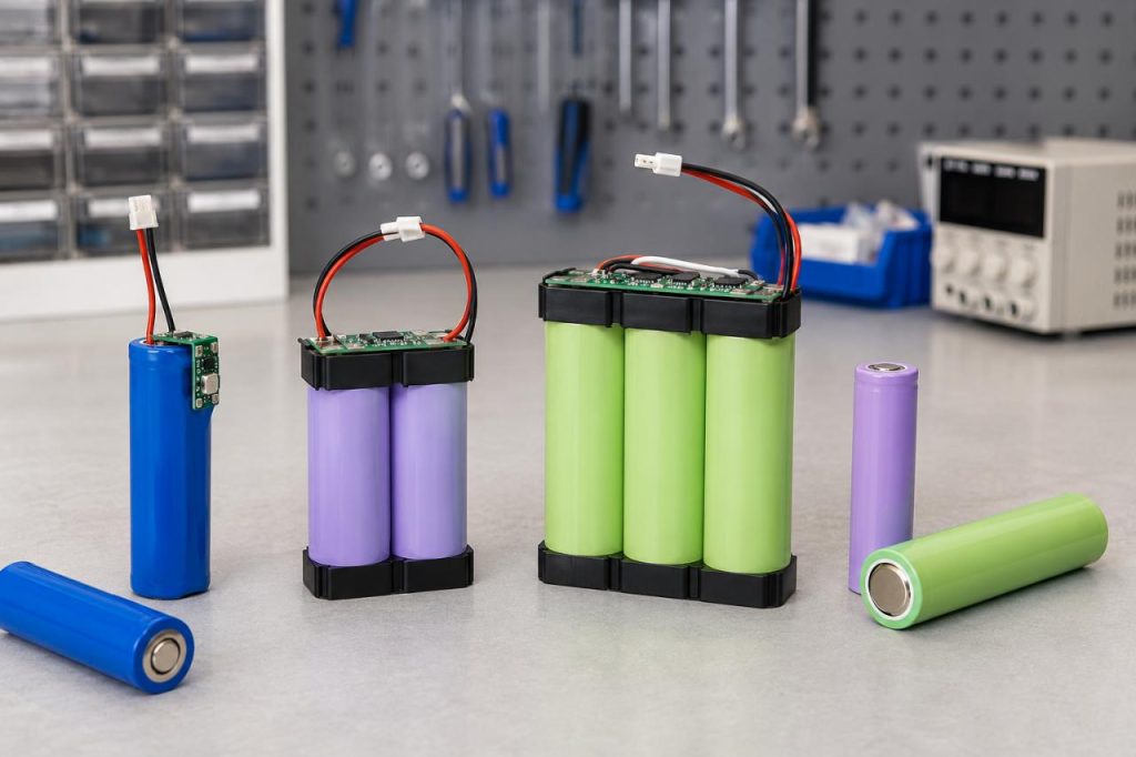
A rectangular layout is suitable for regular battery compartments. A triangular or staggered layout can fit tool housings and irregular internal spaces. Choose a rectangular pack when the device has a flat, box-shaped compartment. It normally offers simpler assembly, insulation, and fixation. Choose a triangular structure when three cells must fit around curved housings or internal components. Choose a staggered layout when the compartment is wider in one area and narrower in another. The correct structure depends on the complete custom cylindrical battery pack dimensions, not only the size of one cylindrical battery cell.
Connector Selection Affects Battery Integration
The connector must fit the device socket and support the required current. Wire length, polarity, and locking structure also affect assembly and operation.
Match the Connector Model and Polarity
Confirm:
- Connector brand
- Connector model
- Number of pins
- Positive and negative positions
- Plug direction
- Anti-reverse design
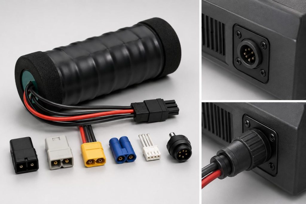
Choose a keyed connector when incorrect insertion could reverse polarity. This reduces wiring and assembly errors. When the device already has a fixed socket, use the exact matching connector model and pin definition. A connector that looks similar may still have a different locking structure or terminal arrangement.
Match the Connector to the Current
Compact two-pin connectors may suit low-current instruments and monitoring equipment. Power tools and industrial devices usually require larger terminals, thicker wires, and stronger locking structures.
Choose a higher-current connector when the device has:
- High continuous current
- Large startup current
- Motor loads
- Heating components
- Frequent peak loads
A small connector may save space, but it should not be used when its current rating is below the device requirement. For devices with motors or startup surges, select the connector according to peak current rather than average operating current. This helps prevent terminal heating, voltage drop, and unstable power delivery.
Confirm Wire Length and Exit Direction
Wires that are too short can create tension on the connector or protection board. Wires that are too long take up space and may interfere with other components. Measure the actual routing path inside the device. Then confirm whether the wires should exit from the top, side, or end of the pack. Choose a locking connector when the device experiences vibration, movement, transportation, or repeated plugging. For a stationary low-current device, a smaller connector may be suitable if it remains secure during normal use.
Custom Cylindrical Battery Pack Requirements Work Together
Voltage, capacity, size, and connector requirements affect one another. Changing one factor may require changes to the entire pack structure.
Match the Configuration to the Requirement
Choose a single 18650 cell for a compact 3.6V device with moderate runtime.
Choose a higher-capacity 18650 cell when more runtime is needed, but the device must retain a similar cell format.
Choose a 1S2P or 1S3P pack when the voltage must stay near 3.6V, but capacity needs to increase.
Choose a single 21700 cell when higher capacity is needed, and the larger cell fits.
Choose a 3S1P pack when the device needs approximately 10.8V and installation space is limited.
Choose a 3S2P pack when the device needs approximately 10.8V, longer runtime, and enough room for six cells.
Choose thicker wires and a higher-current connector when the device has a motor, startup surge, or high peak load.
Avoid Selecting by One Specification
A high-capacity pack may be too large or heavy for the device. A compact pack may not provide enough runtime or output current.
A higher-voltage pack may store more energy, but it cannot be used when the device only supports a single-cell voltage range.
A larger connector may support more current, but it may not fit the available installation area. A smaller connector may fit easily but create excessive resistance or terminal heating under high load.
The correct cylindrical lithium ion battery pack must provide the required voltage and runtime while fitting the installation space and supporting the device current.
Confirm the Battery Specification Before Sampling
A complete specification helps reduce repeated battery samples and structural changes.
Prepare the Electrical Requirements
Confirm:
- Operating voltage
- Acceptable voltage range
- Charging voltage
- Charging method
- Required runtime
- Average power consumption
- Continuous current
- Peak current
These values determine the series and parallel configuration.
Prepare the Structural Requirements
Confirm:
- Maximum length
- Maximum width
- Maximum height
- Preferred 18650 or 21700 format
- Pack shape
- Mounting method
- Wire exit direction
These details determine whether the selected cylinder batteries and supporting components can fit inside the equipment.
Prepare the Connection Requirements
Confirm:
- Connector model
- Pin definition
- Wire length
- Wire gauge
- Locking requirement
- Protection requirements
Start with voltage because it determines the series configuration. Use the required runtime and device power to estimate capacity. Check whether the resulting cell arrangement fits the available space. Then choose wires and a connector that support the operating current, peak load, and assembly method. This selection process helps the custom cylindrical battery pack match the equipment as a complete power system.