
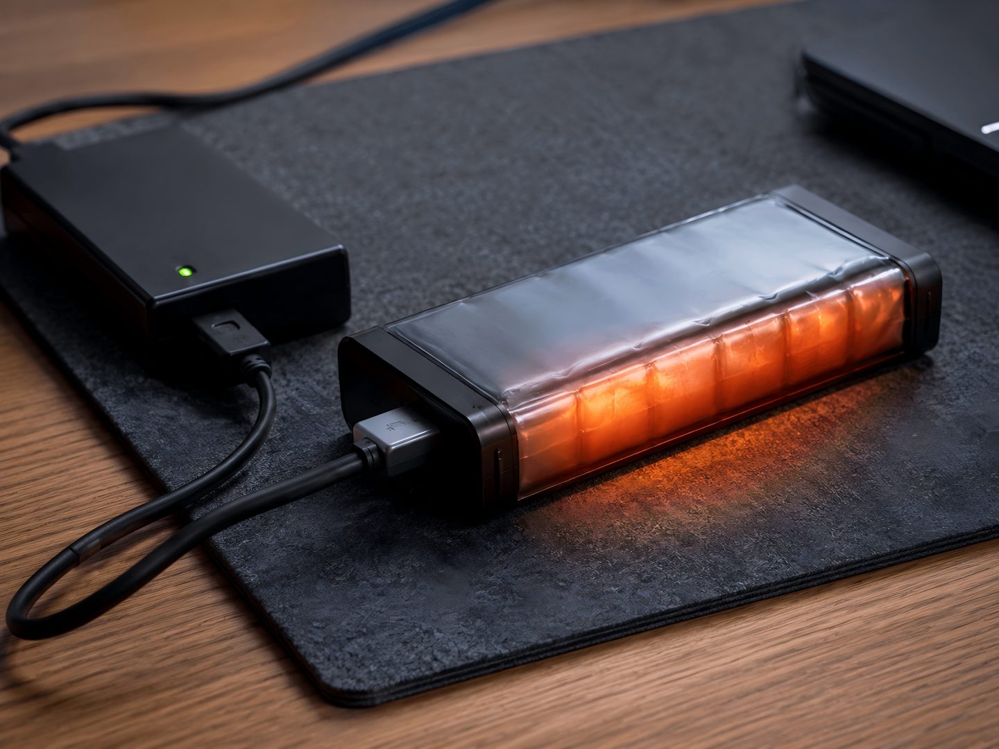
Lithium polymer battery pack clearance leaves little tolerance for dimensional or assembly errors in a thin device. A nominal pouch cell may fit a CAD envelope while the finished assembly does not. Protection electronics, insulation, cable routing, connector position, adhesive, labels, and manufacturing variation all consume space. Charging heat and normal cell expansion also need a controlled mechanical strategy.
The Mechanical Clearance Decision for lithium polymer battery pack clearance
There is no universal clearance value for every pouch battery. The enclosure must accommodate the maximum finished pack, including cell tolerance, protection board, insulation, adhesive, cable routing, connector position, manufacturing variation, and the project-specific allowance for service conditions. The supplier and device team should define and validate that limit together.
The sections below show how to turn the available device space into a measurable battery drawing and assembly requirement.

Define the Device Load and Runtime for pouch battery thickness
Measure sleep, typical, maximum continuous, startup, and pulse current. Record pulse duration and repeated or overlapping functions. Define the lowest device input voltage that supports stable operation and measure voltage at the device terminals.
Use a repeatable duty cycle for runtime tests. Identify the device hardware and firmware, ambient temperature, initial state of charge, active functions, timing, and end condition. Capacity at a light laboratory discharge cannot by itself predict runtime in a device with high pulses or an early voltage cutoff.
Specify the charging source, charge current, termination behaviour, desired charge time, and whether the device operates during charging. These conditions affect cell selection and thermal validation.
Specify the Finished Pack Envelope for the polymer battery pack
Control the maximum dimensions of the complete pack, not only the pouch body. The drawing should define reference points and measurement conditions for length, width, and thickness.
Include:
| Item | Definition required |
| Pouch body | Maximum dimensions and corner profile |
| Seal and tabs | Position, length, keep-out areas, and permitted forming |
| Protection board | Outline, thickness, location, and insulation |
| Wire exit | Direction, bend area, length, and strain relief |
| Connector | Manufacturer, part number, keying, and pinout |
| Finishing | Tape, label, adhesive, pull tab, and insulation |
| Device space | Sharp edges, bosses, heat sources, and pressure points |
Review candidate Polymer Battery options against the complete envelope. A bare-cell drawing should not be used as the finished pack limit.
Plan for Tolerance and Expansion for thin device battery
Avoid using enclosure force to make an oversized pouch fit. Define clearance and retention so the pack cannot move, rub, fold at the seal, or contact sharp features. The design should distribute support across safe areas without concentrated pressure.
Agree on how thickness is measured and which production and service conditions the maximum limit represents. Pouch behaviour depends on cell design, state of charge, age, temperature, load, charging, and abnormal conditions. Mechanical allowances should be established through risk assessment and validation for the exact pack and device.
Do not rely on foam or adhesive to hide an uncontrolled dimension. Specify their material, thickness, position, compression, temperature range, and ageing expectations.
Control Tabs, Wires, and Protection Layout for battery swelling clearance
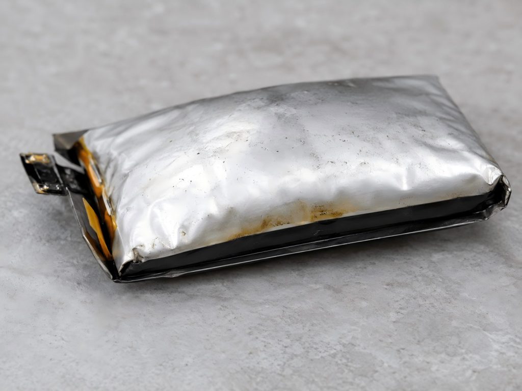
Tabs and seals are functional parts of the cell. Define permitted tab forming, minimum bend radius, insulation, and keep-out areas. The assembly process should not pull, twist, sharply fold, or place tool pressure on the pouch.
Specify wire gauge, length, colour, temperature rating, connector, terminals, crimp method, polarity, and pull-force requirements. Test the complete current path because joints and small connectors can add resistance and heat.
Protection settings need thresholds, tolerances, delays, and recovery conditions. Check overcharge, over-discharge, overcurrent, short-circuit, and temperature functions against valid device behaviour. A normal startup pulse should not create nuisance shutdown.
Custom Battery Pack Solutions can coordinate cell, protection, interface, mechanical, and validation requirements when the pack must be designed around a thin enclosure.
Validate Charging and Heat in the Device for lithium polymer battery pack clearance
The charger, processor, display, radio, LEDs, and battery may heat the same small enclosure. Test at the highest approved ambient temperature and with the functions that create the greatest combined load. Include operation during charging if the product permits it.
Place sensors at defined points on the pouch surface, protection board, connector, charger components, and enclosure. Record input voltage, charge current, termination, time, and temperatures. A single comfortable room-temperature test does not define the operating boundary.
The IEC 62133-2 safety requirements cover portable sealed secondary lithium cells and batteries within their scope. Confirm applicable standards, editions, national requirements, transport documents, and finished-product obligations with qualified specialists.
Test Assembly and Long-Term Mechanical Risk for pouch battery thickness
Use representative enclosure parts and production tools. Verify that operators can install the pack without scraping the pouch, forcing the connector, trapping wires, or bending the protection board. Check retention, drop or vibration behaviour where relevant, service removal, and replacement.
Final validation should use production-representative samples with the planned cell, protection board, wires, connector, insulation, adhesive, labels, assembly process, and factory. Retain the approved sample with its controlled drawing and test reports.
An OEM battery production agreement should define change notification for the cell, pouch construction, tabs, protection components, wires, connector, materials, process, inspection method, or production site.
Provide the Inputs Needed for Pack Selection for polymer battery pack
Submit the device load profile, minimum operating voltage, maximum finished-pack envelope, drawings, wire and connector requirements, charging method, operating and storage temperatures, runtime target, sales markets, and expected order volume. Zenilove can use these inputs to recommend candidate polymer batteries and a production-representative validation plan.
Thin Device Design Questions for thin device battery
Should enclosure clearance be based on nominal pouch-cell thickness?
No. The mechanical design should use the maximum finished-pack dimensions, including pouch, protection board, insulation, adhesive, wires, labels, manufacturing tolerance, permitted expansion, and assembly clearance.
Can foam be used to remove all space around a pouch battery?
Foam may support or retain a pack, but it should not create damaging compression as the pack reaches its maximum approved thickness. Material stiffness, compression set, temperature, aging, and service removal must be evaluated.
Where should battery thickness be measured?
The drawing should define the measurement points, method, equipment, fixture pressure, temperature, state of charge, and stabilisation time. Measurements should cover both the cell body and any local stack-up created by tabs, protection, insulation, or labels.
What should a buyer send Zenilove for a thin-device battery review?
Send dimensioned enclosure drawings, maximum battery envelope, load profile, runtime target, charger, wire and connector details, temperature range, assembly method, service needs, and expected order volume.