
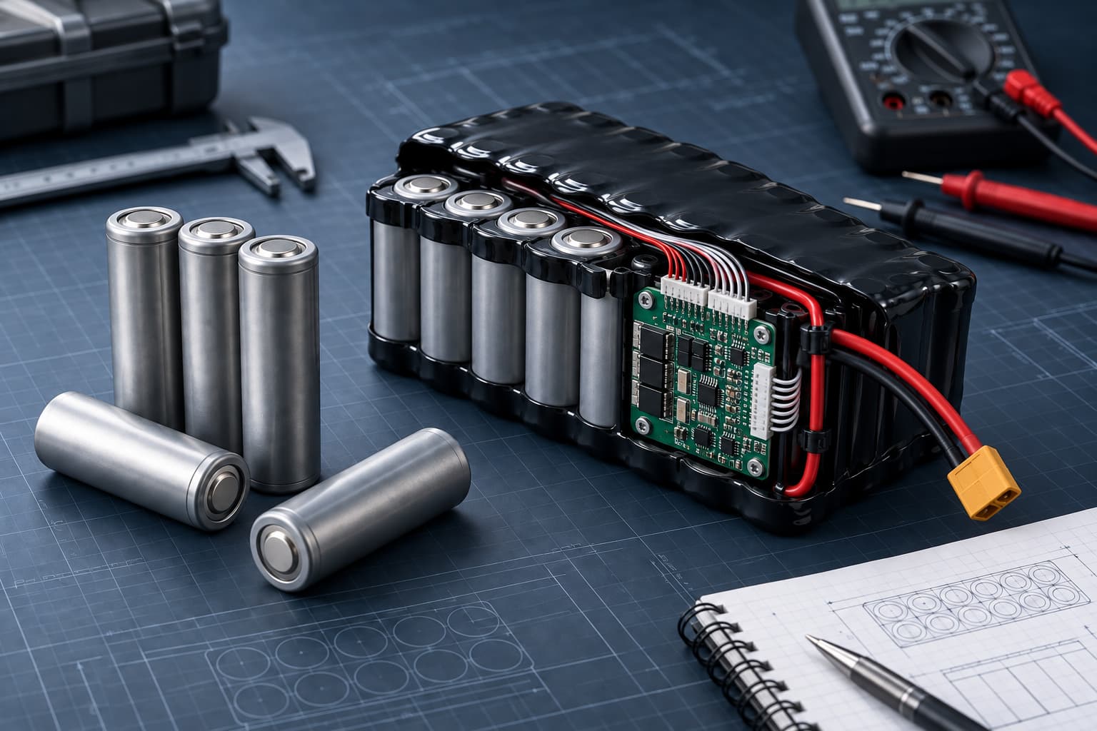
Reliable 21700 battery pack wiring requires more than connecting cells to a positive and negative cable. The design must control cell arrangement, nickel connections, sense-wire order, BMS current rating, wire gauge, connector resistance, polarity, strain relief, insulation, and temperature monitoring. Every part of the current path must support the normal load, startup peak, charging current, operating temperature, and service-life target. A high-capacity pack can still fail in the device when a connector, weld, wire, or protection component creates excessive resistance or triggers an unexpected cutoff.
Define the Electrical Requirements First
Measure the device before selecting the BMS and wiring. Record nominal voltage, complete operating-voltage range, average current, maximum continuous current, startup current, peak duration, charging current, and minimum stable device-input voltage. A 3S 21700 battery pack built from 3.6V cells provides approximately 10.8V nominal and may charge to 12.6V when the selected cells use a 4.2V maximum charge voltage. The equipment must operate correctly across the approved pack-voltage range, not only at the nominal value.
Control the Cell Interconnections
Nickel strips or other approved interconnect materials carry current between cells and series groups. Their material, thickness, width, length, weld pattern, and joint resistance affect voltage drop and temperature rise. Use an approved drawing and work instruction. Control cell orientation, weld location, insulation barriers, fish-paper placement, protection-board position, and spacing from sharp edges. Do not rely on an informal sketch for production assembly. Cells in the same pack should use the approved model and compatible production status. Matching voltage, capacity, resistance, and lot conditions supports more consistent performance, especially when cells are connected in parallel.
Select the BMS for the 21700 Pack
The BMS or PCM must match the series count and cell chemistry. A 3S pack needs monitoring and protection appropriate for three series groups. The design should define overcharge, over-discharge, overcurrent, and short-circuit thresholds, including tolerances, delay times, and recovery behavior. Continuous-current rating alone is not enough. Confirm startup or pulse current and its duration. Protection set too close to normal device demand may cause nuisance shutdowns. A rating that exceeds the capability of the cells, welds, wires, or connector may leave other parts of the pack underprotected.
Cell balancing may help when series groups diverge over time. Temperature monitoring may use an NTC sensor positioned against a defined cell or pack location. Specify the sensor type, resistance curve, tolerance, attachment method, wire routing, cutoff setting, and recovery behavior. The 21700 3S1P battery pack and 21700 3S2P battery pack both use a three-series voltage platform, but their capacity, cell count, current sharing, pack size, and charging current requirements differ.
Choose Battery Wire Gauge
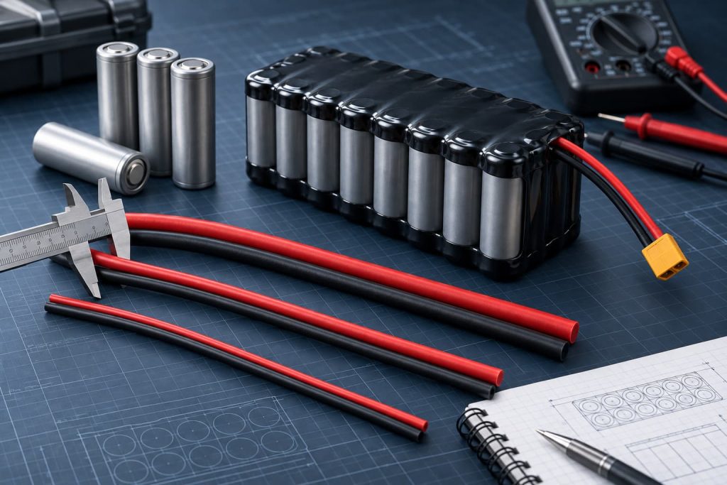
Select wire gauge based on continuous current, peak current, cable length, allowable voltage drop, temperature rating, flexibility, insulation, connector termination, and installation conditions. Longer cables or higher current can increase voltage loss and heat. Measure voltage at the battery output and at the device input during the maximum approved load. Inspect cable and connector temperature during continuous operation and repeated peaks. The final wire length and routing must match the tested production configuration. Sense wires and temperature-sensor wires carry different signals from the main power cables. Route and secure them to prevent abrasion, pinching, reversed order, or connection to the wrong node.
Select the Connector and Pin Definition
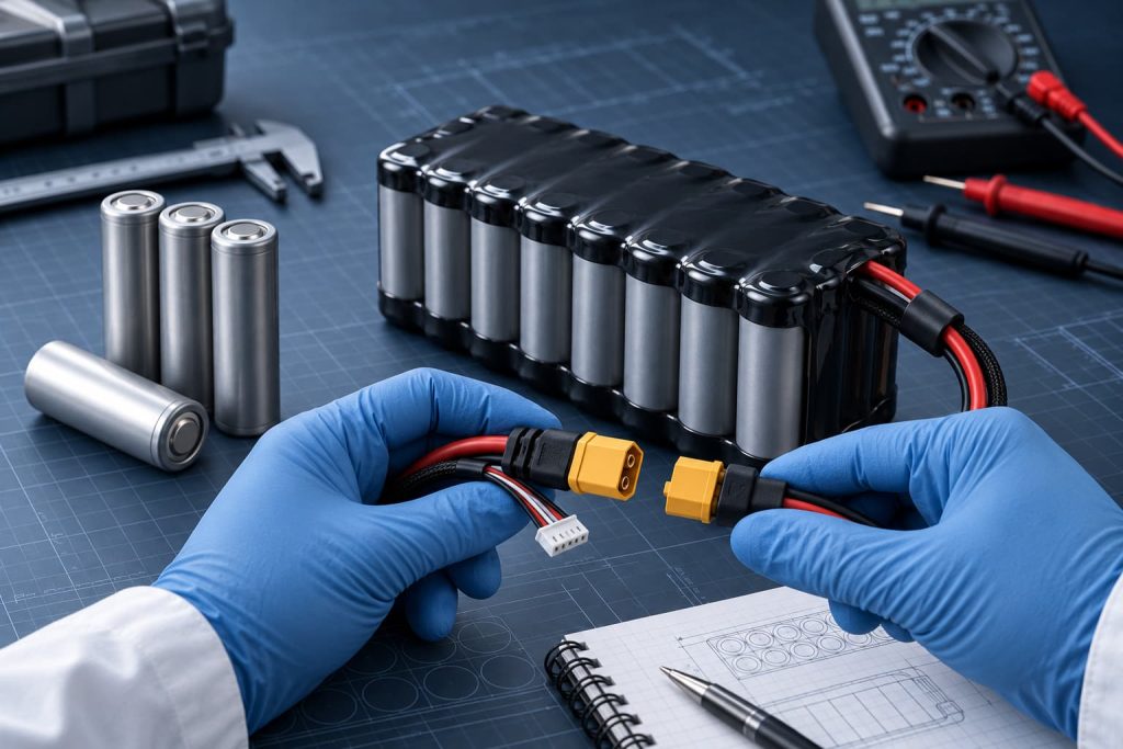
The connector must support continuous current, peak current, voltage, mating cycles, contact resistance, wire gauge, and the device environment. Confirm the exact manufacturer and part number rather than specifying only a connector family.
The drawing should define:
- Connector manufacturer and part number
- Mating connector
- Pin numbering and polarity
- Wire color and gauge
- Wire length and tolerance
- Crimp terminal and crimp requirements
- Locking feature
- Strain relief and cable direction
Use keyed or polarized connectors where practical. Check polarity at assembly, end-of-line inspection, incoming inspection, and device integration. Wire color alone is not sufficient evidence of correct polarity.
Plan the Pack Layout and Cable Exit
A side-by-side pack, triangular pack, or other arrangement changes the available routing space. The 21700 3S1P triangle battery pack places three cells in a compact triangular layout, while a flat arrangement may be better for a wider, thinner enclosure. Define the BMS location, wire exit, bend radius, connector position, maximum finished dimensions, retention method, and installation route. Prevent cable tension from loading welds or circuit-board solder joints. Provide clearance so the enclosure does not clamp the cells or damage insulation.
Validate Wiring in the Finished Device
Build production-intent samples with the approved cells, BMS, nickel, wires, connector, insulation, and enclosure. Test normal operation, repeated startup peaks, maximum continuous load, charging, low-state-of-charge behavior, short-circuit protection, temperature protection, connector heating, vibration, and cable pull conditions. Record individual series-group voltages during charging and discharge. Pack voltage alone can hide one group reaching a limit earlier than the others. Retain sample IDs, cell lots, programmed settings, drawing revisions, crimp records, and test conditions.
Zenilove’s cylindrical battery range provides reference configurations, but final wiring must follow the actual device requirements. The IEC 62133-2 standard covers safety requirements and tests for portable sealed secondary lithium cells and batteries. Other product and transport requirements may apply.
21700 Pack Wiring Questions
Can One BMS Be Used for 3S1P and 3S2P
Both use three series groups, but the required current rating, balancing behavior, connections, temperature design, and charging current may differ. Approve the BMS for the complete pack and load.
How Should Wire Gauge Be Selected
Use measured continuous and peak current, cable length, voltage-drop limit, temperature, connector rating, and installation conditions. Confirm the choice through testing.
What Should Be Frozen Before Production
Freeze the cell model, cell matching limits, BMS hardware and settings, nickel specification, weld pattern, wire, connector, pinout, insulation, drawing, test method, and approved sample IDs.