
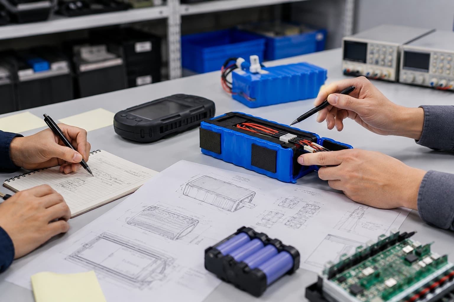
Battery prototyping and design turns device requirements into a battery pack that can be tested, approved, and manufactured consistently. A useful prototype must prove more than voltage and runtime. It should also confirm peak-current performance, charging behavior, protection settings, mechanical fit, connector orientation, temperature response, and assembly quality.
A production-ready prototype uses the intended cell, BMS or protection circuit, wiring, connector, insulation, and mechanical structure. It should pass agreed electrical, mechanical, thermal, charging, and finished-device tests before the project enters mass production.
Define Measurable Battery Prototype Requirements
Start with measured device behavior instead of selecting a battery by capacity alone. Record the device’s sleep current, typical current, maximum continuous current, peak current, and peak duration. Motors, pumps, heaters, displays, and wireless transmissions can create short load peaks that average-current measurements miss.
Runtime also needs a repeatable definition. State the device mode, duty cycle, test temperature, firmware version, initial state of charge, and discharge endpoint. A requirement such as “eight hours of operation” is incomplete unless you define the usage pattern.
The battery prototype requirements should include:
- Nominal and allowable device voltage
- Continuous and peak-current profiles
- Required runtime and test cycle
- Maximum battery dimensions and weight
- Charging source, current, and target charging time
- Operation while charging, if applicable
- Connector, pinout, wire length, and cable direction
- Operating, charging, and storage temperatures
- Communication or fuel-gauge requirements
- Target markets and applicable standards
- Expected annual order volume
These inputs give the battery manufacturer measurable design targets. Teams can also review the battery pack design requirements for compact devices before requesting samples.
Select Cells for Battery Prototyping and Design
Cell selection depends on the load profile, available space, temperature range, cycle-life target, charging method, and supply requirements. Capacity is only one factor. Internal resistance, voltage drop, current capability, dimensional tolerance, and sourcing stability can be equally important.
Cylindrical cells can support applications that need a robust standard format and higher current capability. Polymer cells can fit thin or irregular spaces but require suitable mechanical clearance and edge protection. Buyers can compare different lithium battery products before approving a cell format.
The series count determines pack voltage, while the parallel count affects capacity and current capability. Confirm the complete voltage range rather than checking nominal voltage alone. The device must continue operating during peak loads at a low state of charge.
Test candidate cells under application-specific conditions. Compare:
- Capacity at the specified discharge rate
- Voltage drop during peak loads
- Temperature rise under continuous operation
- Charging behavior inside the enclosure
- Performance at temperature limits
- Dimensional tolerance
- Cycle-life expectations
- Cell traceability and supply stability
Select the cell that meets the complete requirement with an appropriate margin. A larger capacity label cannot correct unsuitable current, temperature, or mechanical performance.
Develop the BMS and Protection Strategy
The BMS or protection circuit must match the selected cell, pack configuration, device load, and charger. Define which functions the battery controls and which functions remain with the host device.
Document the required protection settings, including:
- Overcharge and over-discharge limits
- Continuous-current limit
- Pulse-current limit and duration
- Overcurrent threshold and delay
- Short-circuit response
- Charging and discharging temperature limits
- Thermistor type and location
- Cell balancing for multi-series packs
- Fuel-gauge or communication requirements
Protection thresholds should allow valid startup and operating peaks without exceeding the limits of the cell, wires, connector, or switching components.
Zenilove’s Custom Battery Pack development services cover cell selection, pack configuration, BMS development, mechanical layout, prototyping, testing, and production support.

Control the Mechanical Battery Prototype Design
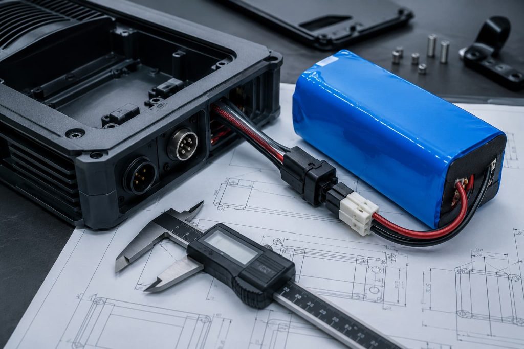
The mechanical drawing should define the maximum finished-pack dimensions. Include the cell, protection board, insulation, tape, label, adhesive, wires, connector, and cable bend area.
Check the complete installation path and the final battery cavity. A pack may fit inside the enclosure but still be difficult to install without pulling wires, scraping a pouch cell, or pressing the battery against a screw or sharp edge.
The controlled drawing should identify:
- Maximum length, width, and thickness
- Connector manufacturer and part number
- Pinout and polarity
- Wire gauge, length, and color
- Cable-exit direction
- Protection-board position
- Insulation and cushioning materials
- Mounting or adhesive requirements
- Critical dimensions and inspection methods
Assign a unique ID to every custom battery prototype. Record its cell model, cell lot, drawing revision, protection-board revision, programmed settings, connector, wire, build date, and approved deviations.
Match each battery sample with the device hardware, firmware, enclosure, and charger used during testing. Without this traceability, a successful result cannot become a reliable production reference.
Complete Battery Prototype Testing
Battery prototype testing should use written methods and acceptance limits. Record the sample ID, test equipment, conditions, raw result, limit, and pass-or-fail decision.
Begin with dimensions, polarity, voltage, and visible workmanship. Continue with capacity, voltage drop, peak current, protection response, standby consumption, and charging behavior.
The finished-device test should cover:
- Device startup
- Maximum operating load
- Defined runtime cycle
- Low-state-of-charge operation
- Charging time and termination
- Charging while operating
- Cell and enclosure temperature
- Connector and wire handling
- Minimum and maximum operating temperatures
Test credible combinations of demanding conditions. Examples include a peak load at low state of charge, charging inside a sealed enclosure, or device startup after low-temperature storage.
A battery may perform correctly on a laboratory bench but show greater voltage drop or temperature rise after installation. The final device, charger, firmware, enclosure, and wiring must therefore be included in prototype validation.
Plan Compliance Before Design Freeze
Start compliance planning during lithium battery prototype development. The applicable requirements depend on the battery type, application, target country, and transport configuration.
For portable sealed secondary lithium batteries, the official IEC 62133-2 specification describes safety requirements and tests for intended use and reasonably foreseeable misuse.
Confirm the required standards, sample quantity, laboratory, documentation, and schedule before freezing the design. Certification samples should represent the intended production configuration. Changes to the cell, protection circuit, or mechanical structure may require technical review or additional testing.

Freeze the Battery Prototype Design
Design freeze means the approved configuration and acceptance criteria are controlled. Future changes can still occur, but they must follow a documented review and retest process.
The design-freeze package should include:
- Electrical specification
- Pack and assembly drawings
- Bill of materials
- Cell and protection-board specifications
- BMS settings or firmware revision
- Connector, wire, pinout, and sensor details
- Test methods and acceptance limits
- Approved sample IDs
- Compliance and transport plan
- Supplier change-notification requirements
Replace vague requirements with measurable values. “Good runtime” should become a defined operating cycle, temperature, firmware revision, cutoff condition, and minimum result.
Confirm Production Readiness with a Pilot Build
A pilot build confirms that the approved battery prototype can be manufactured consistently. Use the intended materials, equipment, work instructions, inspection points, and test fixtures.
Review cell matching, welding, protection-board programming, insulation, cable routing, connector polarity, dimensions, labeling, and end-of-line testing. Investigate failures and rework before releasing mass production.
The battery becomes production-ready when the supplier can reproduce the approved performance within controlled limits. One successful hand-built sample is not enough.
A reliable battery prototyping and design process starts with measured device requirements, continues through cell and BMS selection, validates production-intent samples in the finished device, and ends with design freeze and pilot production. This process gives engineering, procurement, quality, and manufacturing teams the same measurable definition of an approved battery pack.