
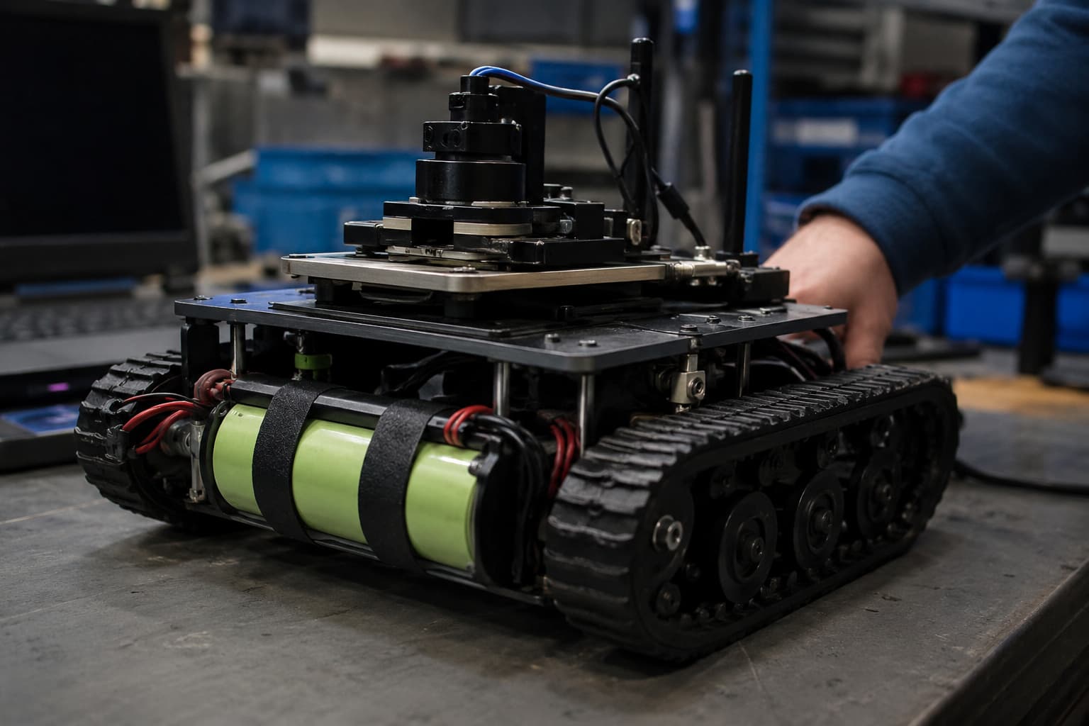
A compact device can accept a lithium battery that fits its cavity and meets its nominal voltage target, yet still fail during charging. The enclosure may become too warm, the battery may stop before reaching full charge, or the protection circuit may disconnect when the device operates during charging. Different adapters and cables can also produce inconsistent results.
These problems usually begin before prototype testing. The battery, charger IC, input source, device load, thermal design, and protection circuit were specified separately instead of as one charging system. OEM teams can reduce redesign work by defining the charging conditions before they approve the battery and enclosure.
This discussion applies to rechargeable lithium-ion and lithium-polymer cells. Primary lithium coin cells require different handling. Never connect a non-rechargeable cell to a charging circuit.
Why Charging Requirements Must Be Defined Before Battery Selection
Charging requirements affect cell selection, PCB design, connector choice, enclosure temperature, and expected charging time. A buyer who sends only voltage, capacity, and size to a battery supplier leaves several system decisions unresolved.
Identify the Charging Source
Start with the power source available to the finished device. Record the input voltage range, current limit, connector type, cable assumptions, and adapter specification. A laboratory supply may charge a prototype correctly while a long cable or restricted USB source causes voltage drop in actual use.
Define Device Operation During Charging
Confirm if the device will remain off, enter standby, or continue working while connected to power. Displays, radios, motors, heaters, and processors can consume part of the available input current. That load changes charging time and may interfere with charge termination unless the electronics include suitable power-path management.
Record the Operating Environment
The team should document ambient temperature, ventilation, charging frequency, and enclosure materials. A charger setting that performs well on an open test board may create excessive heat inside a sealed handheld device. These conditions should become part of the battery request and the prototype acceptance plan.
Which Lithium Battery Charging Parameters Must Be Confirmed?
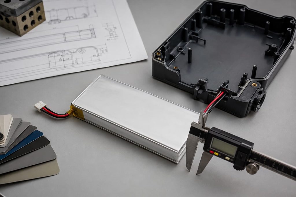
Every rechargeable lithium ion battery needs a charge profile that matches its cell chemistry and manufacturer specification. Nominal voltage does not define the complete profile. The engineering team should approve the following parameters against the selected cell datasheet.
Cell Type and Charge Profile
Confirm the exact cell model and rechargeable chemistry before selecting the charger IC. A Polymer Battery may suit a thin or shaped cavity, yet its allowed voltage, current, and temperature limits still come from its own specification. Do not copy settings from a physically similar cell.
Compact devices may also use a Button Battery for a clock, memory backup, or low-power function. Common primary coin cells such as CR2032 and CR2025 are not rechargeable. Their presence in a device does not justify connecting them to the main charging path.
Maximum Charge Voltage
Set the charger voltage to the cell manufacturer’s stated limit. Include charger accuracy, component tolerance, and voltage measurement error in the review. A small voltage difference can change delivered capacity, cell stress, and protection behavior. Firmware should not override the approved cell limit.
Charge Current and Charging Time
Define current in relation to the cell’s rated capacity and allowed charge rate. Faster charging can raise battery and PCB temperature. Lower input power can extend charging time or prevent the charger from maintaining its programmed current. Estimate charging time with the real device load included, then confirm it on samples.
Termination and Recharge Conditions
The specification should state how the charger determines charging is finished, the termination-current setting, and the condition for restarting a charge. A device that continues drawing power can keep measured current above the termination threshold. The result may be a long constant-voltage stage or repeated charging behavior.
Charging Temperature Range
Define the permitted cell-temperature range and how the system responds outside it. Confirm the sensor type, its placement, and its contact with the cell. A sensor located near a warm processor may report board temperature instead of battery temperature, while a sensor far from the cell can react too slowly.
How Compact Device Design Changes the Charging Strategy
Small enclosures place the cell, charging circuit, processor, wireless module, and display within a limited area. Their combined heat and current demand can change a charging design that looked acceptable during separate component tests.
Enclosure Space and Battery Placement
Leave suitable mechanical clearance around the cell and avoid pressure from screws, sharp edges, or rigid components. Check connector orientation, wire length, bend radius, and assembly access. The production drawing should reflect real tolerances, not just nominal battery dimensions.
Thermal Conditions Inside the Device
Measure cell, charger IC, and enclosure temperatures under the highest expected ambient conditions. Test the device in its final housing with normal covers, seals, and insulation installed. If heat from the processor or radio reaches the battery, the charging current may need to be controlled based on temperature or operating state.
Connector and Power-Path Design
Verify that connectors, cables, PCB traces, and protection components can carry the planned current without excessive voltage drop or heat. Devices designed to operate during charging need a defined power path so system load and battery current remain measurable and controlled.
What Lithium Battery Charging Protection Should the System Include?
Charging control and battery protection perform different jobs. The charger manages the normal charge profile. A PCM or BMS responds to specified abnormal electrical conditions. Treating the protection circuit as the normal charge controller can produce repeated cutoffs and added cell stress.
Electrical Protection
Confirm overvoltage, overcurrent, and short-circuit response across the battery pack and device. Review the charger input limit, pack protection thresholds, wiring, connector rating, and fault-recovery method together. The thresholds must suit the selected cell and expected load, not a generic pack design.
Temperature Monitoring
The charging system should respond predictably when cell temperature moves outside the approved range. The response may include reducing current, pausing charging, or requiring the temperature to return to an acceptable range before restart. Test the actual sensor placement because enclosure heat can change its reading.
Single-Cell and Multi-Cell Responsibilities
A single-cell device and a series-connected pack do not require the same monitoring architecture. Series packs may need individual cell-voltage monitoring and balancing. The battery supplier and electronics team should document which functions sit in the charger, pack electronics, and device firmware.
Product and market requirements also affect the validation plan. IEC 62133-2 addresses safety requirements for portable sealed secondary lithium cells and batteries. The applicable standards still depend on the device category, battery configuration, and sales market, so teams should confirm the required scope before tooling.
How Should Lithium Battery Charging Be Tested Before Production?
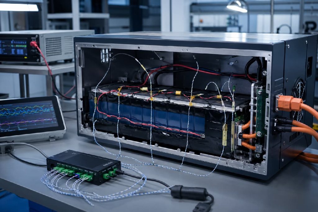
Datasheet review cannot prove that a finished compact device will charge correctly. Validation must use production-intent batteries, electronics, cables, adapters, firmware, and enclosures. Define measurable pass criteria before the first formal test.
Verify the Charge Profile on Samples
Record battery voltage, input current, battery current, temperature, and charging time from a low state of charge through termination. Confirm current transitions, maximum voltage, termination behavior, and recharge behavior. Test more than one sample so a single favorable unit does not hide tolerance problems.
Test Real Input Sources and Device Loads
Repeat tests with approved adapters and representative cables at the permitted input limits. Run the device in standby and its highest expected operating mode. Check wireless transmission, display activity, motor startup, or other peak-load events that may compete with charging power.
Check Thermal and Abnormal Conditions
Test the closed enclosure at the planned ambient-temperature limits. Include interrupted power, repeated cable connection, sensor faults covered by the design, and protection activation. Verify that the device recovers in a controlled state instead of entering an endless restart or charge cycle.
Set Production Acceptance Criteria
Translate the approved sample results into limits that production teams can check. Useful criteria include charger output, standby current, sensor response, connector polarity, pack protection function, and charging status indication. Record the battery model and approved component revisions to prevent unreviewed substitutions.
Common Lithium Battery Charging Mistakes in OEM Projects
Charging faults often come from incomplete specifications rather than defective cells. The following mistakes create avoidable prototype revisions and supplier disagreements.
Copying a Generic Charger Setting
Teams sometimes select a charger from nominal voltage alone. This ignores the exact cell limit, charge rate, termination behavior, temperature range, and accuracy requirements. Approve settings only after selecting the cell.
Selecting Current Only for Speed
A high current target may reduce early charging time while increasing thermal load. Input limits and the constant-voltage stage can reduce the expected time saving. Measure the complete cycle inside the final enclosure before approving the setting.
Freezing the Enclosure Before Thermal Testing
An enclosure may fit the battery but provide poor heat separation from the charger IC or processor. Validate charging with production-intent mechanical parts before final tooling. Mechanical changes become slower and more expensive after that point.
Expecting the Protection Board to Fix Charger Errors
A protection cutoff shows that the system crossed a fault threshold. It should not occur during routine charging. Repeated trips call for a review of charger settings, load behavior, wiring, cell selection, and thermal conditions.
Reviewing Compliance After Prototype Approval
Late compliance review can force changes to cell choice, protection, enclosure, documentation, or testing. Confirm the target markets and product category while defining the charging specification.

Clear Lithium Battery Charging Requirements Reduce Device Risk
A compact device needs a written lithium battery charging specification that links the selected cell to the electronics and real operating conditions. Record the cell model, maximum charge voltage, charge current, termination method, temperature range, power source, device load, protection responsibilities, and test limits.
Before approving tooling or mass production, ask the battery supplier and device engineering team to sign off on the same values. Test the complete device with production-intent parts and document the acceptance criteria. Projects that need coordinated cell selection, pack electronics, connectors, structure, and validation can define those items through Custom Battery Solutions before sample approval.