
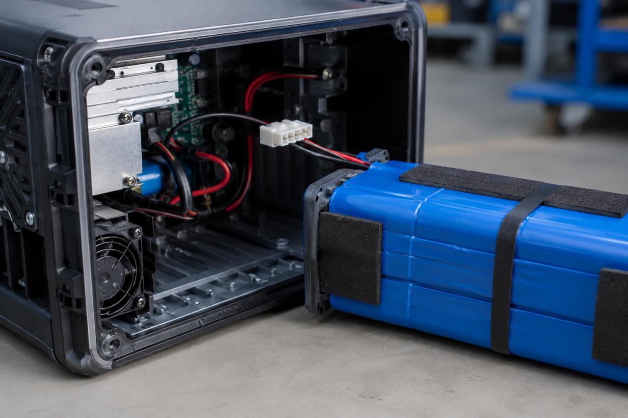
A Custom Battery Pack project should not enter prototype production as soon as voltage, capacity, and dimensions are available. These values do not show whether the battery can support the actual load, fit the available space, work with the charger, or meet later testing requirements. Starting too early can cause repeated samples, enclosure changes, charging problems, and delays. Before requesting a custom lithium battery pack, define what the battery must achieve, which limits cannot change, and what information the supplier must provide.
Define Custom Battery Pack Operating Requirements
The battery must support the complete operating cycle, not just average power consumption.
| Requirement | Information to Confirm |
|---|---|
| Voltage | Nominal voltage, operating range, and shutdown voltage |
| Current | Normal, startup, peak, and standby current |
| Duty cycle | Duration and frequency of each operating mode |
| Runtime | Required operating time between charges |
| Temperature | Operating, charging, and storage ranges |
A motor, wireless module, or bright display may create short current peaks that average data cannot show. Provide measured load data when possible and separate confirmed values from estimates.
Check Whether the Required Runtime Is Practical
Runtime depends on the duty cycle, usable energy, conversion losses, temperature, and device shutdown voltage.
| Runtime Factor | Question to Confirm |
|---|---|
| Duty cycle | How long does each operating mode last? |
| Usable energy | How much nominal energy can the device use? |
| Conversion loss | How much energy is lost through regulators? |
| Temperature | Will the environment reduce capacity? |
| Shutdown voltage | At what voltage will the device stop? |
Ask the supplier to explain the runtime calculation. A larger capacity may extend runtime, but it can also increase size, weight, charging time, and cost. Review these trade-offs before confirming the battery pack design.
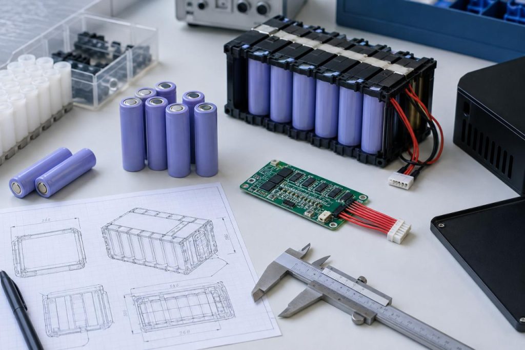
Set the Custom Battery Pack Size and Structure
The supplier needs more than maximum length, width, and height. The installation plan should leave enough space for cables, connectors, screws, circuit boards, and nearby components.
| Mechanical Requirement | Details to Provide |
|---|---|
| Installation space | Available dimensions and shape |
| Dimension limits | Fixed, preferred, and adjustable measurements |
| Cable and connector | Outlet direction, position, and access space |
| Mounting | Adhesive, bracket, screw, slot, or enclosure support |
| Service access | Installation, removal, and replacement needs |
| Environment | Expected vibration, impact, or compression |
A battery may meet the stated dimensions but still create wire, connector, or assembly problems.
Request a drawing before prototype assembly. Confirm the connector position, wire length, cell arrangement, insulation, mounting method, and assembly clearance.
Decide Which Dimensions Can Change
| Status | Meaning |
|---|---|
| Fixed | Cannot change because it affects the product structure |
| Preferred | Should stay near the target but can be adjusted |
| Adjustable | Can change within a stated range |
Limited flexibility can provide more cell options and a simpler pack structure. Do not approve a complicated arrangement only to preserve a dimension that does not affect the finished product.
Confirm Custom Battery Pack Charging and Protection
The battery, charger, and device must follow the same charging plan. Confirm which component controls charging and fault recovery.
| Charging Requirement | Information to Confirm |
|---|---|
| Charger input | Voltage and available current |
| Charging time | Target time for a full charge |
| Temperature | Charging range and sensor position |
| Use while charging | Whether the device operates during charging |
| Fault recovery | Behavior after overheating or interrupted charging |
These details help the supplier design a rechargeable battery assembly that works with the device and charger.
| Protection Function | Item to Review |
|---|---|
| Overcharge | Cutoff voltage and recovery condition |
| Over-discharge | Cutoff voltage and restart behavior |
| Overcurrent | Threshold and delay time |
| Short circuit | Detection and recovery method |
| Temperature | Sensor position and limits |
| Cell balancing | Whether balancing is needed |
A current limit set too low may interrupt normal operation. A limit set too high without reviewing the cells, wires, connector, and temperature may not provide suitable protection.
Finalize Connectors and Communication Before Prototyping
Connector changes after the first sample can affect resistance, battery dimensions, assembly, tooling, delivery time, and cost.
| Connector Item | Information Required |
|---|---|
| Part number | Exact connector and mating connector |
| Pin definition | Pin quantity, function, and polarity |
| Cable | Length and wire size |
| Direction | Orientation inside the device |
| Retention | Locking or fastening method |
Photos should not replace an exact part number or drawing.
Define Battery Communication Requirements
Some products only need power wires. Others require temperature sensing, battery identification, state-of-charge reporting, fault messages, or communication with the battery management system.
| Communication Item | Requirement to Confirm |
|---|---|
| Protocol | SMBus, I²C, UART, CAN, or another interface |
| Reported data | Voltage, current, temperature, charge level, health, or faults |
| Failure response | Device behavior when communication stops |
| Firmware | Which side manages the protocol |
| Calibration | Required accuracy and method |
Confirm these requirements before building the battery prototype. A late change may require a different protection board, connector, wiring, firmware, and enclosure layout.
Review Safety, Testing, and Supplier Deliverables
The sales region, shipping method, storage conditions, and operating environment may affect cell selection, construction, labeling, packaging, and documentation.
For portable sealed secondary lithium cells and batteries, IEC 62133-2 covers safety requirements and tests for intended use and reasonably foreseeable misuse. The applicable standards still depend on the finished product, market, application, and shipping method.
| Supplier Deliverable | What to Confirm |
|---|---|
| Specification | Voltage, capacity, current, and temperature limits |
| Drawing | Dimensions, tolerances, wire position, and connector direction |
| Cell information | Cell model, chemistry, and approved alternatives |
| Protection settings | Cutoff values, delays, and recovery conditions |
| Tests and documents | Testing, labels, packaging, reports, revisions, and exclusions |
The quotation should identify included items, exclusions, revision costs, and testing fees.
| Validation Test | What It Should Confirm |
|---|---|
| Runtime | Required operating time |
| Startup and peak load | Stable voltage under high current |
| Charging | Time, temperature, and cutoff behavior |
| Protection | Response to abnormal conditions |
| Communication | Stable data exchange |
| Installation | Connector fit, cable routing, and enclosure clearance |
| Handling and storage | Performance after vibration, impact, or storage |
The device turning on does not mean the prototype has passed validation. Each test needs a defined method, operating condition, sample quantity, and acceptance limit.
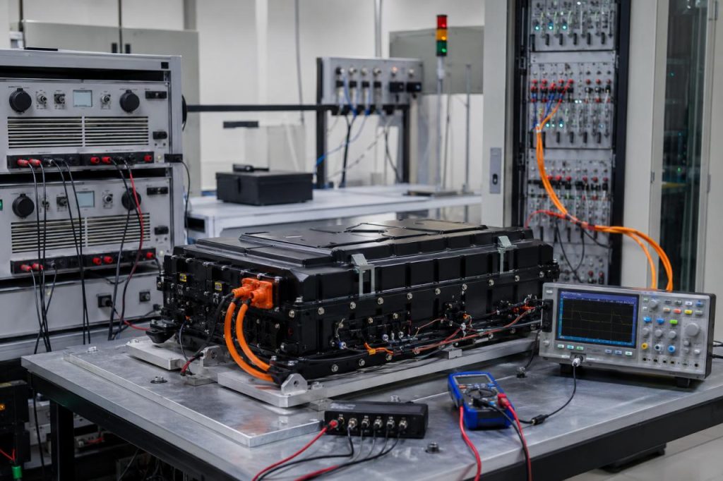
Clear Requirements Produce a Reliable Custom Battery Pack
A reliable Custom Battery Pack begins with clear operating, mechanical, charging, connector, safety, and testing requirements.
| Review Area | Final Confirmation |
|---|---|
| Electrical | Voltage, current, shutdown voltage, and runtime |
| Mechanical | Dimensions, mounting, wire direction, and connector position |
| Charging and protection | Charger parameters, cutoff values, and responsibilities |
| Communication | Protocol, reported data, and failure behavior |
| Validation | Test methods, sample quantity, acceptance limits, and records |
| Commercial scope | Prototype quantity, revisions, documents, and exclusions |
The final decision should not depend only on capacity, prototype price, or delivery time. Review whether the proposal explains how the battery will work inside the actual device and whether the design is supported by drawings, calculations, specifications, and a test plan. After the prototype passes validation, confirm how the approved OEM battery pack will move into production. The cell model, protection board, connector, wiring, insulation, firmware, tooling, assembly process, and production location should remain under change control. This keeps the approved battery structure consistent from prototype samples through production.