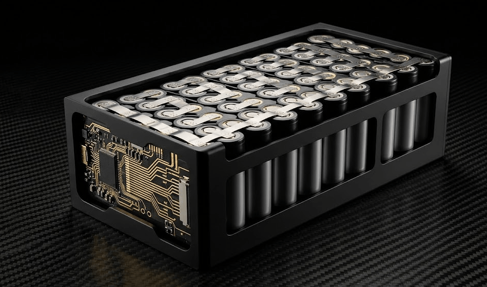
A lithium ion cell pack combines individual cells — typically 18650 or 21700 format — with a dedicated Battery Management System (BMS) to deliver high energy density, precise voltage control, and safe operation in demanding industrial environments. Basically, it is the engineered backbone of reliable power for robotics, medical devices, and rugged electronics.
Why Upgrade to a Lithium Ion Cell Pack from NiMH or Lead-Acid Batteries?
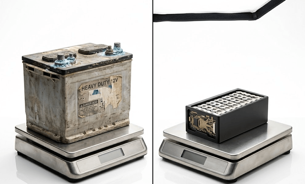
The short answer: weight, density, and runtime. Ultimately, the real case for lithium is not a single metric — it is, in fact, a compounding advantage across every parameter that matters in industrial design.
Lead-acid packs carry an energy density of roughly 30–50 Wh/kg. A modern lithium-ion cell pack, by contrast, delivers 150–265 Wh/kg. That represents a 3× to 5× improvement. Therefore, an autonomous mobile robot that previously needed a 20 kg lead-acid bank to complete an 8-hour shift can, as a result, achieve the same runtime with under 7 kg of lithium cells.
NiMH packs perform better than lead-acid on a weight. However, they still carry two stubborn penalties: the memory effect and a self-discharge rate around 20–30% per month. Lithium-ion self-discharge, on the other hand, sits closer to 1–3% per month. Consequently, that distinction becomes critical for medical devices and standby power systems where long shelf readiness is non-negotiable.
Lithium Ion Battery Pack Benefits for Hardware Engineers and Procurement Teams
Switching chemistry touches three areas directly: enclosure size, thermal budget, and total cost of ownership. Specifically, a smaller, lighter pack reduces structural load in mobile platforms, cuts enclosure volume, and lowers shipping costs across product lifetimes. Furthermore, for hardware engineers designing the next generation of industrial IoT devices, that freed volume often goes toward sensors or connectivity hardware. Overall, the chemistry upgrade pays for itself faster when the system runs multiple shifts per day or sits in standby for weeks between deployments.
| Specification | Lead-Acid / NiMH | Lithium Ion Cell Pack |
|---|---|---|
| Energy density | 30–80 Wh/kg | 150–265 Wh/kg |
| Cycle life (to 80%) | 200–500 cycles | 500–2,000+ cycles |
| Self-discharge / month | 5–30% | 1–3% |
| Memory effect | Moderate (NiMH) | None |
| Operating temp range | −20°C to 45°C | −40°C to 60°C |
| Gravimetric footprint | High | Up to 70% lighter |
How to Configure Series and Parallel Connections in a Lithium Ion Battery Pack
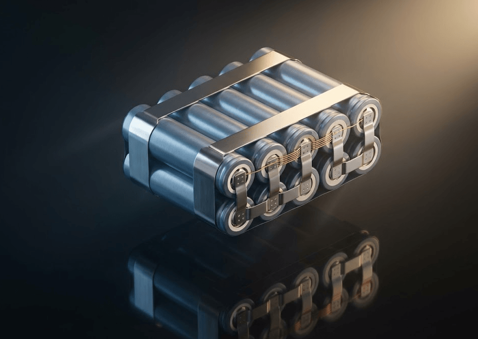
Cell configuration is the primary design lever engineers use to match a lithium ion cell pack to device voltage and capacity requirements. Essentially, two rules govern everything.
Series connections (xS) add voltage. Specifically, four 3.6 V cells in series produce a 14.4 V pack — standard for many robotics platforms. Parallel connections (xP), meanwhile, add capacity. For example, four cells of 3,000 mAh in parallel remain at 3.6 V but deliver 12,000 mAh. In practice, real-world packs combine both approaches. A 4S3P configuration, therefore, contains 12 total cells running at 14.4 V nominal with triple the single-cell capacity. As a result, this topology is common in multi-cell battery assemblies for industrial handheld devices and collaborative robot end-effectors.
- Series raises voltage, not capacity:Increasing the number of batteries in series to meet 24V, 36V, or 48V system requirements will not extend runtime. Voltage and capacity are two independent parameters.
- Parallel requires matched cells: Batteries in the same parallel battery pack must come from the same production batch, and their internal resistances must be matched. Mismatched batteries will generate balancing currents when stationary, accelerating battery performance degradation and creating hot spots.
- BMS cell count must match topology:The Battery Management System (BMS) independently monitors each series-connected battery pack; a 4S BMS cannot safely manage a 6S battery pack. This incompatibility is one of the main causes of warranty issues in custom designs.
For guidance on selecting the right topology, Battery University’s series and parallel configuration guide provides a rigorous technical reference widely used by power electronics engineers.
Custom Lithium Ion Cell Pack Configurations for Industrial Applications
Standard S×P topologies cover most voltage and capacity requirements. However, certain industrial applications demand configurations that go beyond cell count alone. Basically, true custom configuration means engineering the entire pack architecture around the deployment environment — not just the electrical spec. Moreover, for engineers evaluating custom lithium ion battery solutions, three scenarios clearly show where bespoke design delivers measurable value over off-the-shelf options.
Medical devices operating in cold storage environments
Portable diagnostic equipment and infusion pumps often move between room-temperature operating areas and cold storage below 10°C. As a result, standard NMC chemistry loses significant capacity below 0°C. Consequently, a custom pack for this application uses LFP cells with a low-temperature electrolyte formulation, a self-heating circuit controlled by the BMS, and a conformal-coated PCB rated for condensation exposure. Ultimately, the result is consistent runtime across the full thermal range — not just in the lab.
AMRs requiring opportunity charging at high C-rates
Autonomous mobile robots in warehouse environments rarely complete a full charge cycle. Instead, they dock for 8–12 minutes between runs. Therefore, a custom pack for this duty cycle uses high-power NMC cells rated for 3C–5C continuous charge, wider nickel bus bars to handle peak current without resistive heating, and a BMS configured for partial-state-of-charge operation. Cycle life is preserved precisely because, in this case, the pack was designed for partial DoD from the start — not adapted from a standard design after the fact.
Industrial handheld devices with non-standard form factors
Rugged barcode scanners, field calibration instruments, and pipeline inspection tools often have enclosures where a rectangular prismatic pack simply does not fit. In response, Zenilove engineers custom cell arrangements using pouch or prismatic cells in L-shaped, curved, or split configurations. Additionally, the BMS mounts separately on a flexible harness, keeping electronics away from mechanical stress points. Therefore, the pack survives drop cycles and vibration profiles that would delaminate a conventional design.
How does the BMS prevent thermal runaway?
- Overcharge and over-discharge cutoff:The over-discharge cutoff function can protect the battery structure at the low voltage end, preventing copper dissolution and lithium deposition, thereby avoiding internal short circuits caused by long-term accumulation.
- Overcurrent and short-circuit protection:When a fault current is detected, the discharge field-effect transistor turns on within microseconds. This response speed is sufficient to protect the battery before it accumulates a large amount of heat.
- Thermal monitoring and cutoff:The NTC thermistors distributed across the battery array report the temperature to the BMS MCU. If any sensor exceeds 60°C during continuous operation, or exceeds 70°C at peak temperature, the BMS will immediately stop charging or discharging.
What is the real cycle life in industrial use?
Specification sheets cite cycle life under ideal laboratory conditions: room temperature, 1C charge rate, 100% depth of discharge, and a standard CC-CV profile. Industrial applications, however, rarely match those conditions. Therefore, the published cycle count and the field cycle count diverge — sometimes significantly. Nevertheless, a well-specified NMC lithium ion cell pack rated at 500–800 cycles to 80% capacity can exceed 1,200 cycles in practice, provided three parameters are managed deliberately.
Reduced depth of discharge extends life non-linearly
Cycling to 80% DoD instead of 100% DoD can double usable cycle life. Furthermore, cycling to 50% DoD can triple it. Many industrial applications — AMRs running opportunity charging, medical devices docked between procedures — already operate at partial DoD by default. Consequently, engineers who size the pack correctly for partial DoD consistently see field life that far exceeds datasheet minimums.
Charge voltage ceiling management
Charging NMC cells to 4.10 V rather than 4.20 V costs roughly 5–7% of nominal capacity. In return, however, it reduces calendar degradation substantially. For devices that remain plugged in between deployments — medical carts, fixed industrial terminals — capping charge voltage is, therefore, one of the most effective life-extension strategies available without any hardware changes.
Operating temperature discipline
Sustained operation above 40°C accelerates electrolyte oxidation and SEI layer growth. Specifically, a pack logging 35% of its cycles above 45°C can reach 80% capacity in half the expected cycle count. As a result, thermal design of the host enclosure becomes a battery life variable — not just a reliability concern. For that reason.

Conclusion
A lithium ion cell pack is a system-level decision, not a parts swap. Lithium delivers 3× the energy density of legacy chemistries at a fraction of the weight. Series and parallel topology sets the voltage and capacity foundation. Custom configurations adapt that foundation to environments where standard designs fall short. A capable BMS holds the entire system inside safe operating limits. Manage depth of discharge, charge voltage, and temperature correctly, and a well-built pack consistently outlasts its rated cycle life. The chemistry is mature. The engineering is proven. What separates good outcomes from poor ones is how deliberately the pack was designed for the application.